Hydrodynamic challenges with azimuthing thruster propulsion
Azimuthing thrusters are common propulsion units for a variety of ships as they offer compact arrangement, possibility of vector thrust, high propulsive efficiency and subsequent lower power/fuel consumption.
An additional advantage is the dual purpose of propulsion of speed and/or station-keeping/positioning at zero speed. Some important issues related to better hydrodynamic performance are outlined below.
Pod alignment with the incoming flow
In order to reduce the unnecessary additional drag due to misalignment, pod units need to be aligned with the incoming flow.
Typically, pods are designed as a twin-screw propulsion system, hence each pod is located off-centreline of the vessel where the inflow is strongly asymmetrical due to the shape hull surface and the flow boundary layer effect. Therefore, an effort needs to be made for alignment of the pod against the local flow. This can be accomplished by either a RANS CFD-based approach (numerical calculations) or a physical streamline visualization test.
An advantage of the former is low cost and broad volume of the investigated streamline while the latter approach includes the suction effect of the operating propeller.
We recommend a combined approach where the local streamlines are first investigated by means of CFD (prior to model testing) and later verified by physical streamline test during the test program. The final tuning of the alignment is checked during the self-propulsion test where the pod operates at a controlled range of small azimuth (“rudder”) angles, and the propeller power is measured. The angular position with minimum power indicates the best alignment. Current experience indicates that power savings in the range of 1-3% can be achieved by adequate alignment of the thruster/pod.
Optimum propeller direction of rotation
Due to the asymmetric propeller wake for wing thrusters, determining the favourable propeller direction of rotation may be feasible in view of powering optimisation. In this case, the propeller rotational induced flow losses could be reduced by utilizing the available pre-swirl (non-zero average tangential in-flow) into the propeller disk.Normally, this is experimentally verified by conducting a brief propulsion test (typically at design speed only) where the propeller direction of rotation is consecutively varied, and among the tested propeller directions, the direction chosen is the one found best in terms of minimum total required power. The energy-saving potential of selecting propeller direction of rotation is relatively modest, and based on our experience could typically range from 0.5 to 1.5%.
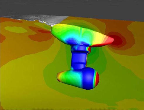
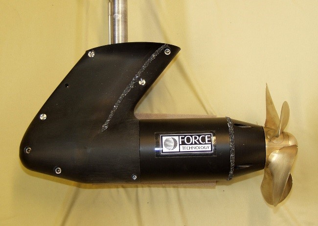
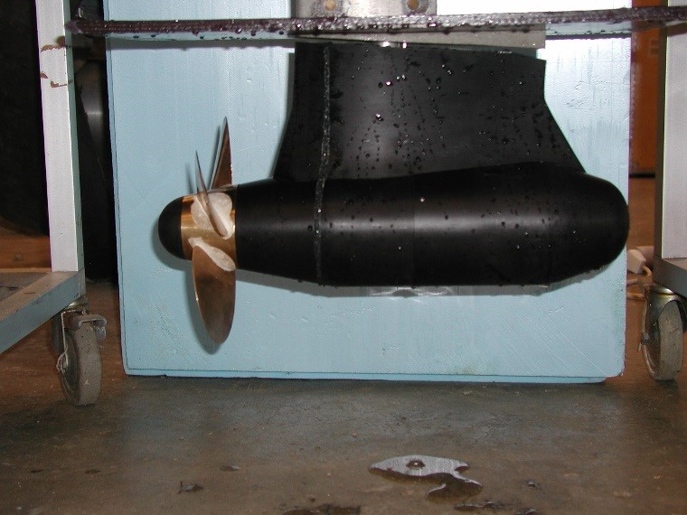
Appendages
Thruster head-boxes contribute with a major appendage resistance component and require special attention in the design process. Good alignment with the local flow could be achieved both with RANS CFD and paint streamlines visualization test, preferably accounting for the operating thruster/propeller.Being located close to the free surface, the thruster head box influences not only the frictional and form (pressure) resistance components, but also significantly contributes to the wave-making resistance.
Since the introduction of thrusters and pods as main propulsion units, FORCE Technology has been in the forefront with the development of state-of-the-art measuring equipment, data acquisition systems and technical procedures for hydrodynamic model testing of thruster units and pods.
Because of our acquired technical means as well as knowledge and experience, numerous hydrodynamic model tests with azimuthing thrusters and pods have been successfully accomplished for clients worldwide.

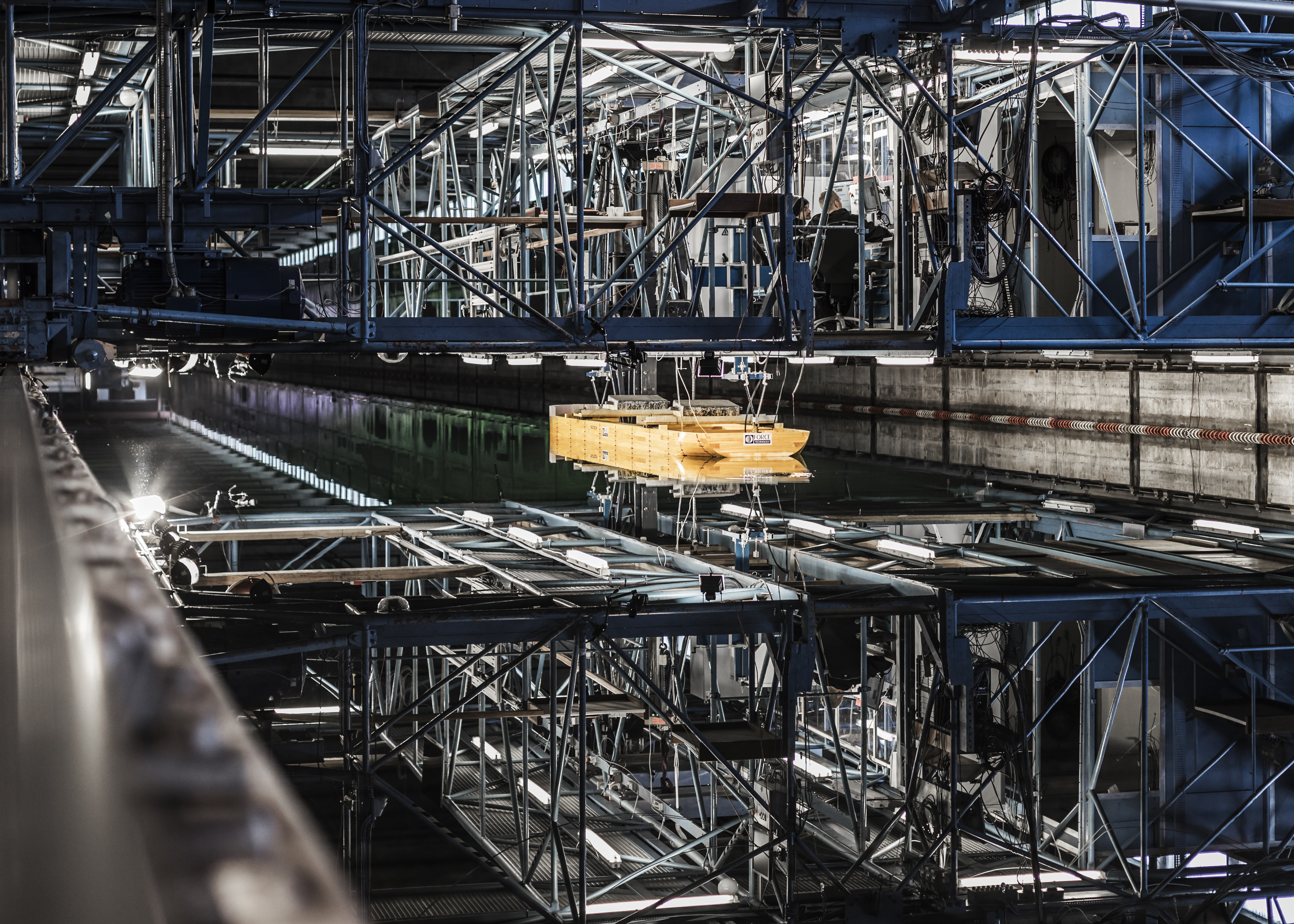
Facility
Towing tanks
POD propulsion
Article